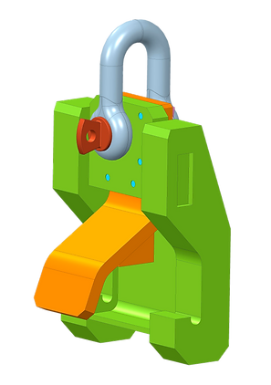


3D modeling
Creo Parametric
Inventor

Solid state 3D modeling
Creating accurate geometry regardless of the complexity of the model;
Automatic scaling of thumbnails for quick and easy reuse;
Quick creation of such design elements as rounding, chamfers, holes, etc .;
Creating detail options using family tables.

Assembly modeling
Intellectual capabilities for working with assemblies;
Creating simplified ideas "on the fly";
Share lightweight but accurate model views with the Shrinkwrap tool;
Effective real-time detection of intersections.

Detailed documentation, including 2D and 3D drawings
Creation of 2D and 3D-drawings according to internal standards, including ASME, ISO, JIS, ESKD;
Automatic creation of associative material specifications (BOM) with notes;
Automate the creation of drawings and templates

Technical creation of surfaces
Development of surfaces with complex geometry using sweeps, blends, extends, offsets, as well as a wide range of specialized tools;
Surface trimming / lengthening using tools such as extrude, revolve, joining and stretching;
Perform surface operations such as copy, merge, expand, and transform;
Problems of geometry of complex surfaces.

Free modeling of surfaces
Rapid creation of free surfaces and shapes using sub-divisional modeling capabilities;
High quality parameterized surfaces can be used immediately in the process of detailed 3D design;
Multi-level modeling with unbundling for great opportunities for surface control, which allows you to change the details without affecting the existing shape;
Parametric control of free geometry by synchronization with existing curves or edges with touch control.

Modeling of sheet steel components
Creating walls, fungus (bends), through holes (punches), notches, notches, shapes and reliefs (reliefs) using a simple user interface;
Automatic creation of flat patterns from 3D geometry;
Apply a wide range of bending tolerance to create flat product models.

Modeling of welded joints and structures
Optimized user interface for designing structural frameworks;
Setting requirements for connections;
Obtaining from the model such valuable information as mass properties, tolerances, intersections and cost;
Easy creation of 2D documentation for welded joints;
Intelligent component library and automatic creation of materials for faster creation of designs than when using standard techniques.

Data exchange
Work with various standard file formats, including STEP, IGES, DXF, STL, VRML, AutoCAD DWG, DXF (3D import with associated 2D), ACIS import / export, Parasolid import / export;
Convert, using Unite technology, data from other CAD systems, including: CATIA, Siemens NX, SolidWorks, Autodesk SolidEdge.
Incorporate non-PTC Creo data directly into these models without creating additional business objects or files;
Support for the export of non-PTC Creo formats (CATIA, Siemens NX, SolidWorks) and their corresponding updating with the help of paid funds.